Resilient Couplings
Ressiliant Couplings is an amalgamation of the benefits of high power rating of gear coupling and flexibility of nylon or Rubber coupling with elevated evaluation. These are simple to maintain and install. The flexible grids are smoothly replacable with no disturbing connected drives. Boson Resellient Couplings are availabe in a wide range of sizes covering from 0.006 to 3.505 RMP/ HP with bores up to 265 mm.
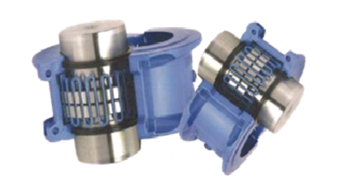
Horizontal Cover Type
Horizontal covers are designed for ease of assembly and removal, particularly in tight spaces, as they can be put on after the hubs and grid spring element have been already assembled.
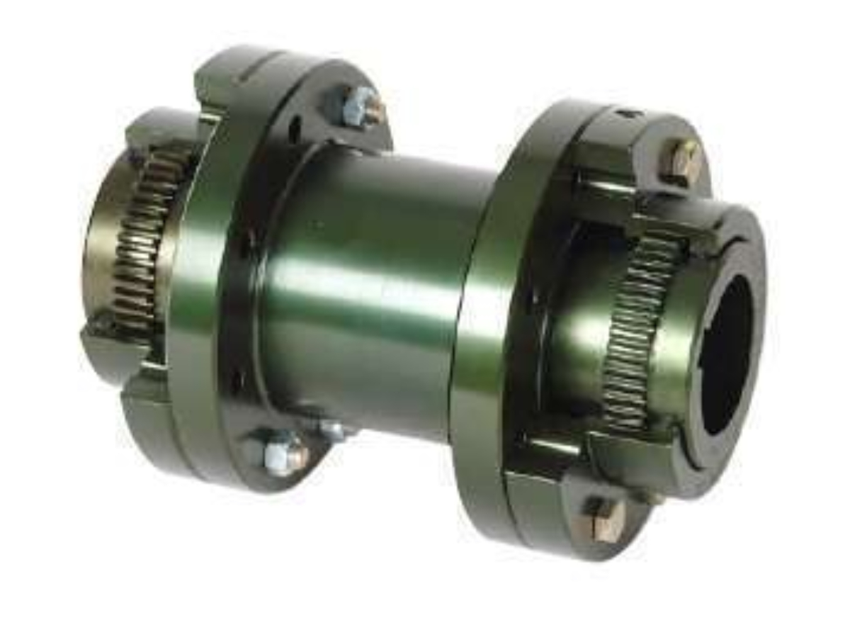
Vertical Cover Type
Vertical split cover designs require putting the split covers on the shaft prior to putting on the shaft hubs and grid spring element. Once the hubs and grid spring element have been attached, the vertical split covers can then slid over the hubs and grid spring element and fastened together. (This also means that to completely remove a vertical split cover off a shaft, the grid spring element and coupling hubs would have to first be removed.)
The benefit of the vertical split cover design is that it can operate at a higher maximum speed (RPMs).. Based on your application, it may be required to go to a vertical split cover design if the horizontal cover design maximum speed is too low.
Spacer Type
Spacer Type are designed for ease of assembly and removal, particularly in tight spaces, as they can be put on after the hubs and grid spring element have been already assembled.
Brake Drum Type
Brake drum type cover designs require putting the split covers on the shaft prior to putting on the shaft hubs and grid spring element. Once the hubs and grid spring element have been attached, the Brake drum type covers can then slid over the hubs and grid spring element and fastened together. (This also means that to completely remove a vertical split cover off a shaft, the grid spring element and coupling hubs would have to first be removed.)
Taper Grid Type
Used frequently in many mill applications, taper bored mill motor hubs allow for rapid mounting and removal without damaging the shaft or bore. Hubs are available to suit standard AISE mill motor frames or can be produced to suit non standard tapers.
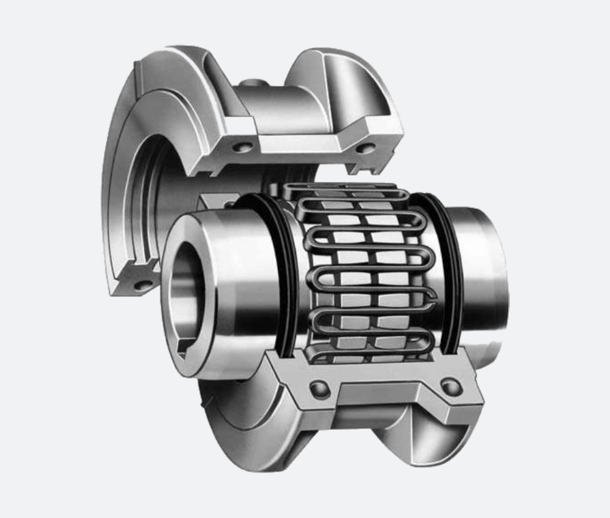
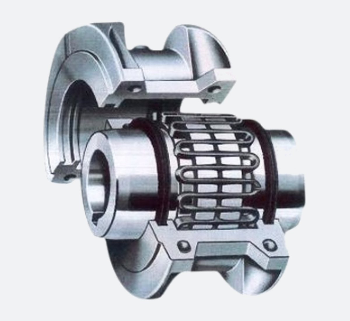
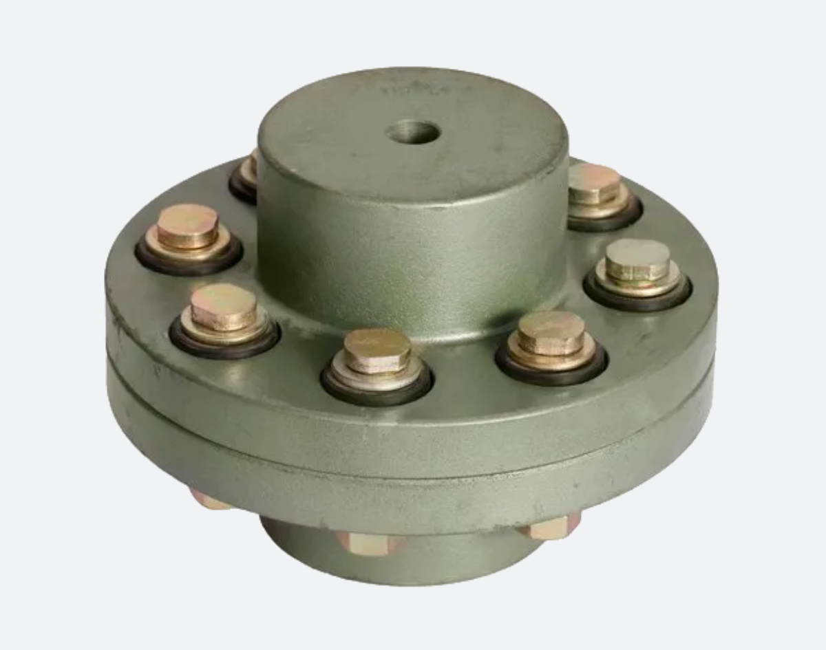
Construction
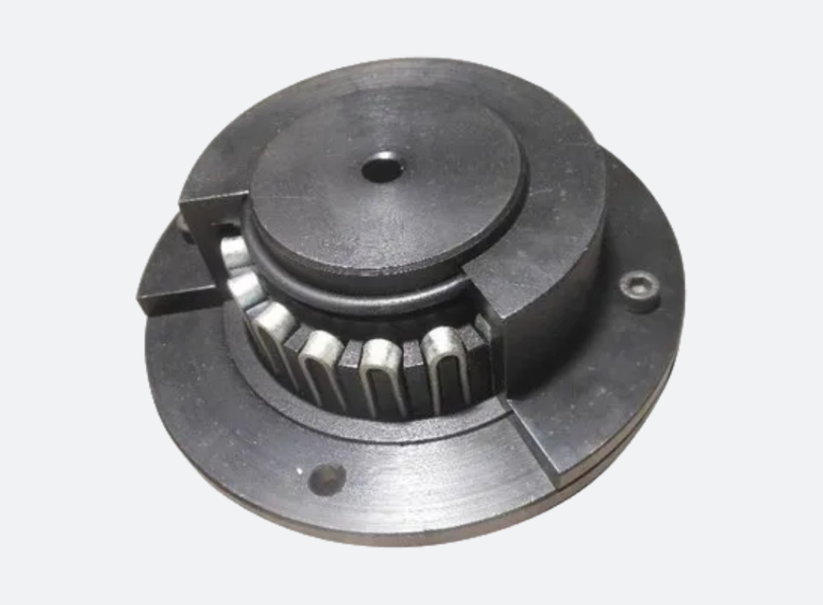
Boson High torque Resilient Coupling having a grid spring which connects two hubs ,driving and driven. The spring is specially designed considering the requirement of the driving and driven equipments.
The Grooves on the hubs are little flared to allow the grid members to play during the torque transmitting.
The basic principle of design in Resilient Coupling, makes it capable to accommodate axial, parallel and angular misalignment between a driving and driven equipments.
Features
- All Metal Construction having no fast wearing out components
- Torsionally flexible Transmit full torque with dampened vibration and deduced peak load.
- Accommodates angular, parallel and axial misalignment.
- High ratings.
- Versatile design and interchangeability
- Easy assembly and maintenance
- Very low Downtime.
- Longer service life.
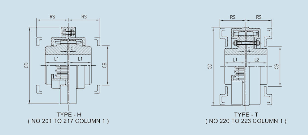
| Coupling No. | Rating HP/RPM | Clear Dia. OD (MM) | Boss Length L1 (MM) | Boss Length L2 (MM) | Removal Space RS (MM) | Gap G (MM) | Cover Bore CB (MM) | Safe Speed RPM | Stock Rough Bore (MM) | Bore Max. (MM) | Approx. Weight KGS |
|---|---|---|---|---|---|---|---|---|---|---|---|
| 201 | .006 | 105.0 | 38.0 | 38.0 | 52 | .85 | 44.52 | 5650 | 10 | 29 | 3 |
| 202 | .010 | 120.5 | 38.0 | 38.0 | 52 | .85 | 58.80 | 4750 | 12 | 38 | 4 |
| 203 | .020 | 144.5 | 44.5 | 44.5 | 59 | .85 | 62.00 | 4450 | 16 | 41 | 5 |
| 204 | .030 | 171.5 | 51.0 | 51.0 | 59 | .85 | 87.45 | 3400 | 16 | 57 | 9 |
| 206 | .045 | 190.5 | 51.0 | 51.0 | 79 | .85 | 84.25 | 3200 | 16 | 54 | 11 |
| 207 | .065 | 197.0 | 57.0 | 57.0 | 79 | .85 | 96.95 | 2950 | 16 | 64 | 15 |
| 208 | .095 | 222.0 | 63.5 | 63.5 | 79 | .85 | 119.20 | 2500 | 25 | 78 | 20 |
| 209 | .125 | 254.0 | 70.0 | 70.0 | 80 | .85 | 143.00 | 2150 | 25 | 92 | 27 |
| 210 | .185 | 276.0 | 89.0 | 89.0 | 80 | .85 | 165.20 | 1900 | 25 | 108 | 43 |
| 211 | .355 | 295.0 | 102.0 | 102.0 | 128 | 1.60 | 155.70 | 1800 | 38 | 102 | 54 |
| 213 | .455 | 324.0 | 101.5 | 101.5 | 147 | 1.60 | 187.46 | 1650 | 50 | 123 | 63 |
| 214 | .655 | 336.5 | 101.5 | 101.5 | 147 | 1.60 | 184.28 | 1550 | 50 | 121 | 72 |
| 215 | .905 | 375.0 | 114.5 | 114.5 | 147 | 1.60 | 222.38 | 1350 | 50 | 146 | 104 |
| 217 | 1.255 | 425.5 | 127.0 | 127.0 | 147 | 1.60 | 254.00 | 1200 | 50 | 167 | 149 |
| 220 | 1.755 | 432.0 | 140.0 | 140.0 | 179 | 3.20 | 239.50 | 1200 | 75 | 157 | 175 |
| 221 | 2.405 | 432.0 | 140.0 | 140.0 | 179 | 3.20 | 239.50 | 1200 | 75 | 157 | 180 |
| 222 | 2.755 | 492.0 | 152.5 | 152.5 | 179 | 3.20 | 266.70 | 1100 | 85 | 173 | 207 |
| 223 | 3.505 | 492.0 | 152.5 | 152.5 | 179 | 3.20 | 266.70 | 1100 | 85 | 173 | 216 |